ERD and Relational Schema#
The purpose of the ERD and Relational Schemas are to design and represent the database that forms your application’s datastore (model).
Database Design Scenario
The first step in designing a database is developing an understanding of the scenario. For learning about designing databases we will use the following example:
Student Subject Database
Students can log into to access:
their current enrolment
subject grades when entered
Teachers can log into to:
Enter student grades
Each subject is only offered once, with one teacher
Each student can enrol in each subject only once.
EDR — Entity Relationship Diagram#
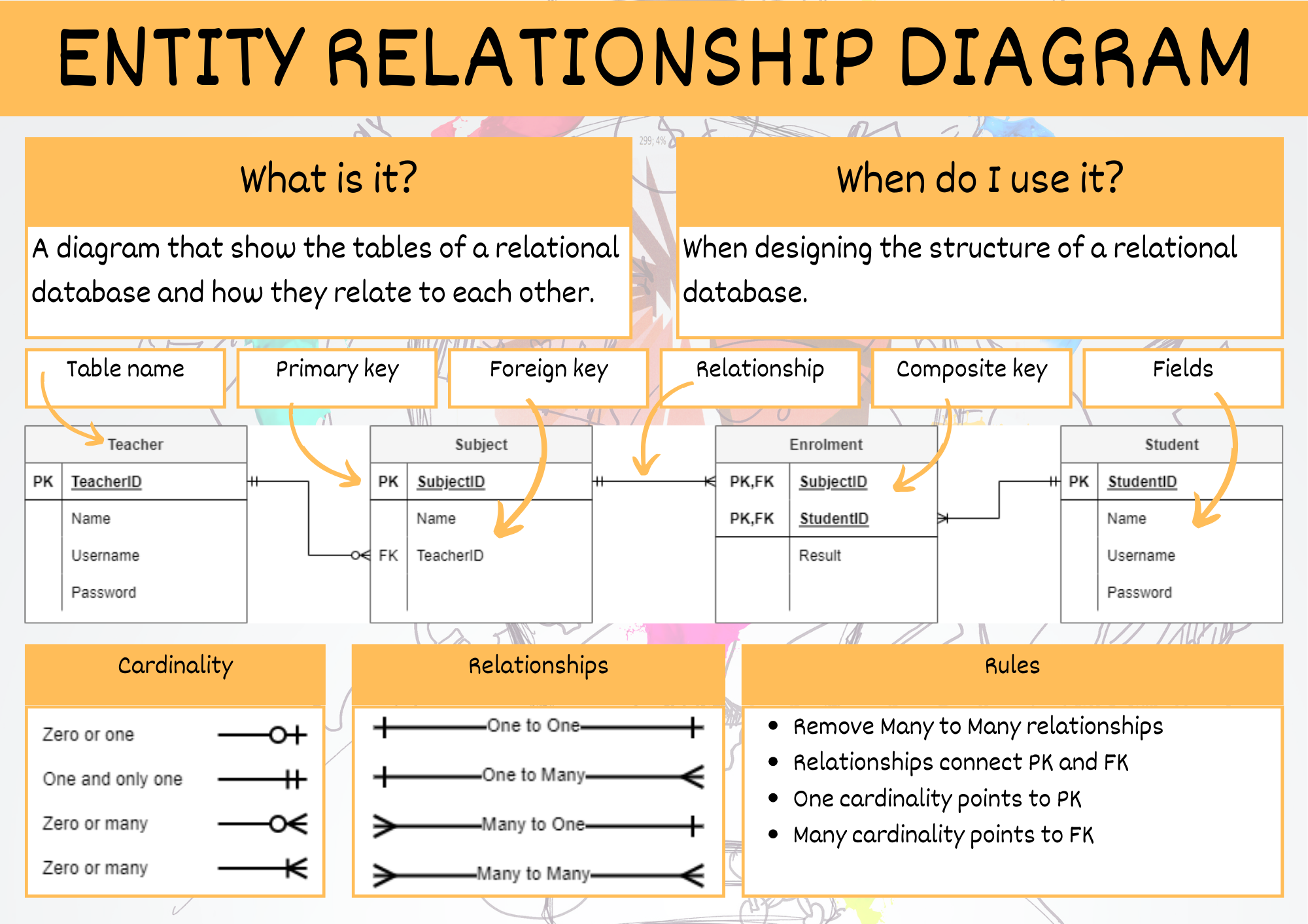
An Entity Relationship Diagram (ERD) is a type of flowchart that illustrates how “entities” such as people, objects or concepts relate to each other within a system. [LucidChart, 2017]
In following the process of creating a ERD, you will create a relational database that complies with rules to the level of Third Normal Form.
Watch the videos below to understand designing an ERD.
We will use the following steps to create our Entity Relationship Diagrams, using the Student Subject Database as an example:
Step 1: Identify the entities#
Look at the scenario and the data needs and identify all the entities that the database needs to store. Entities can be people, places, things or processes.
In the Student Subject Database we have the following entities.

Step 2: Add attributes#
Refer back to your data needs and requirements and add the relevant attributes to each entity.
The Student Subject Database ERD after stage 2:

Step 3: Establish relationships and cardinality#
The next step is to create the connection between the entities. First connect the related entities using lines. Then establish the cardinality by working out the range of connections each entity can have to the second entity.
For example in the Student Subject Database:
teacher subject relationship
each teacher can teach zero to many subjects (assuming you can have teachers who do not teach for this time period)
each subject has one and only one teacher who teaches it
student subject relationship
each student can study zero to many subject (assuming a student can be enrolled but not studying)
each subject can have zero to many students studying it (assuming a subject can exist without students studying it)
You will end up with the following ERD

Step 4: Resolve many-to-many relationships#
In this course we will use bridging entities to deal with many-to-many relationships.
To do this:
find a many-to-many relationship
place a bridging entity between the two
the bridging entity will have a composite key, so use the correct table
reconnect the relationships
establish the new cardinality
the cardinality will be a many on the bridging entity’s side, and a one on the original entities’ sides
enter the primary keys from the original entities as the two parts of the composite key for the bridging entity
add any other relevant attributes
For our Student Subject Database:
the subject / student relationship is a many-to-many
add a bridging entity between the two, and named ‘Enrolments’
if you can’t think of an appropriate name, just combine the name of the two original entities
connect the relationships from the Enrolments entity to the Subject entity and the Student entities
the new cardinalities will be many on the Enrolments entity end, and one on both the Subject entity and the Student entity
SubjectID and StudentID are entered as the two parts of Enrolments’ composite key
the attribute of Results is added to Enrolments
At the end of step 4 our ERD looks like this:

Step 5: Identify the foreign keys#
Identifying the foreign keys establishes how the different entities are connected together. If there is a relationship drawn between entities, then there must be a primary key / foreign key connection.
Steps to establish foreign keys
choose a relationship
check the table on the many end for an attribute that naturally connects to the other entity
ensure that the name of the foreign key reflects the primary key.
if you can’t find one, you should add an attribute and name it after the primary key of the other entity
place a FK in front of the foreign key attribute
move the relationship so that it connects the foreign key to it respective primary key
Our Student Subject Database example at the end of step 5:

Sample Tables#
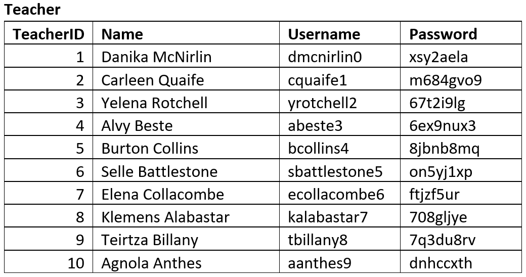
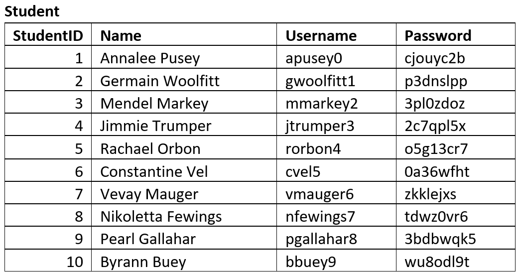
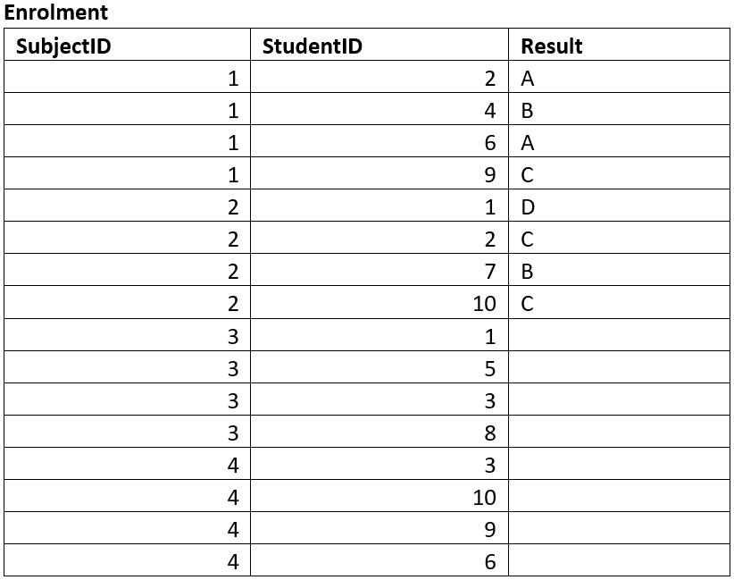
Sample tables are used to ensure that the database structure that the ERD produced can effectively store the required data adequately.
You should create tables that reflects the entities identified and attributes identified by the ERD. Then fill the table with sample data. This data may be given to you, or you may produce mock data that is representative of data that will be stored in the database. A good resource for creating mock data is mockaroo.
Below are the sample tables for the Student Subject Database.


EDR Summary#

Relational Schema#
To convert your final, adjusted ERD to a Relational Schema (RS) you will need to identify the datatype of each field.
We will be using SQLite which provides the following data type options:
INTEGER: signed integers
REAL: floating point values
TEXT: text strings
BLOB: a blob of data, stored exactly as it was input
Since Diagram.net does not provide a three column entity table, we will separate the attribute name and data type using the | symbol.
The RS for the Student Subject Database will look like:

